SwitchBlox for Ardupilot
BotBloxBelow are the available bulk discount rates for each individual item when you purchase a certain amount
- Buy 10 - 19 and get $6.50 off
- Buy 20 - 49 and get $12.50 off
- Buy 50 - 99 and get $15.00 off
- Buy 100 - 199 and get $16.00 off
- Buy 200 or above and get $17.50 off
SwitchBlox, Built for the Ardupilot Ecosystem
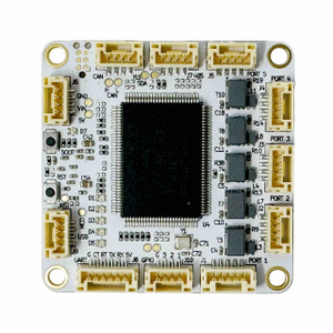
Ethernet is quickly becoming the go-to communication bus for drones and robots, and is starting to see more widespread adoption into the Ardupilot ecosystem. To make achieving ethernet communication backbones in Ardupilot systems easier, BotBlox has release SwitchBlox Ardupilot.
SwitchBlox Ardupilot is a modified version of our 5 port 10/100Mbps ethernet switch, SwitchBlox, that uses the 4 pin JST-GH 1.25, for easy connectivity to other Ardupilot compatible hardware.
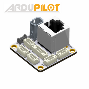
When used with our Ardupilot Cable Adapter and the included cable set, SwitchBlox Ardupilot can be used with all available Ardupilot hardware that currently uses ethernet.
Ardupilot Compatible Hardware
Newly released Ardupilot devices are starting to see 10/100BASE-TX (10/100Mbps ethernet) incorporated for high speed communications with more advanced sensors. Connecting all these devices together in a drone requires the use of an ethernet switch. SwitchBlox Ardupilot is designed to provide this functionality in an incredibly compact (1.75 inch x 1.75 inch) square, at a low cost and with minimal setup required.
Leveraging our existing SwitchBlox design, which has seen 1000s of flight hours, SwitchBlox Ardupilot provides an easy way to add an ethernet backplane to any Ardupilot powered drone or robot.
Plug and play network switch
As an unmanaged network switch, it works straight out the box, all you need to do is...
- Apply a 8 to 60V DC supply.
- Connect your devices using the included cable set.
- It will automatically begin forwarding packets, no coding or setup needed.
SwitchBlox Ardupilot also has a 5V 2A output for powering small nearby devices. This 5V input can also be used as an auxilliary 5V input to supply the board. Make sure to only use either the 8-60V input OR the 5V Auxilliary input, but not both at the same time.
Board Map
Connector type and pinout
Ethernet Connector
SwitchBlox Ardupilot uses the following connector on board for the five ethernet ports and single power output. This connector system features positive locking and is common in Ardupilot hardware.
Connector On Board: BM04B-GHS-TBT(LF)(SN)
Mating Connector: GHR-04V-S
Mating Connector Crimp: SSHL-002T-P0.2
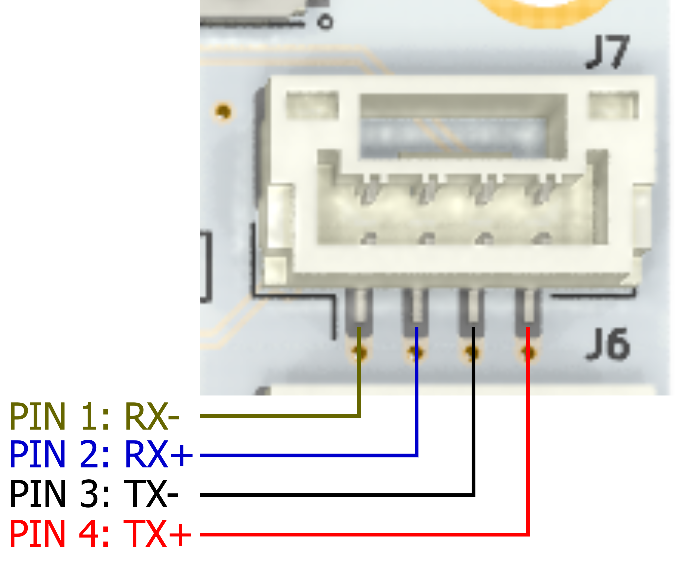
RX = Receive, input to SwitchBlox Ardupilot
TX = Transmit, output from SwitchBlox Ardupilot
Note, SwitchBlox Ardupilot automatically detects incorrectly connected RX/TX pair and polarity mismatches with a connected device, and will correct its own port connections in this case. This process (part of the ethernet autonegotiation functionality) means you can use a straight or crossover cable, and don't need to worry if you misconnect the polarities of the ethernet signals.
Power Input Connector
Connector On Board: Solder Pads, 2.4mm x 3.5mm with a 1.2mm plated hole
Mating Connector: Bare wires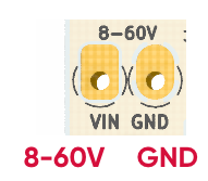
For power input, SwitchBlox Ardupilot is designed to have power wires soldered directly to the power pads. Alternatively, a 3.5mm pin pitch screw terminal can be soldered to the pads for a more easily removable connection. We recommend the 284391-2 from TE Connectivity for this screw terminal
5V Power Output (5V Aux Input) Connector
Connector On Board: BM04B-GHS-TBT(LF)(SN)
Mating Connector: GHR-04V-S
Mating Connector Crimp: SSHL-002T-P0.2
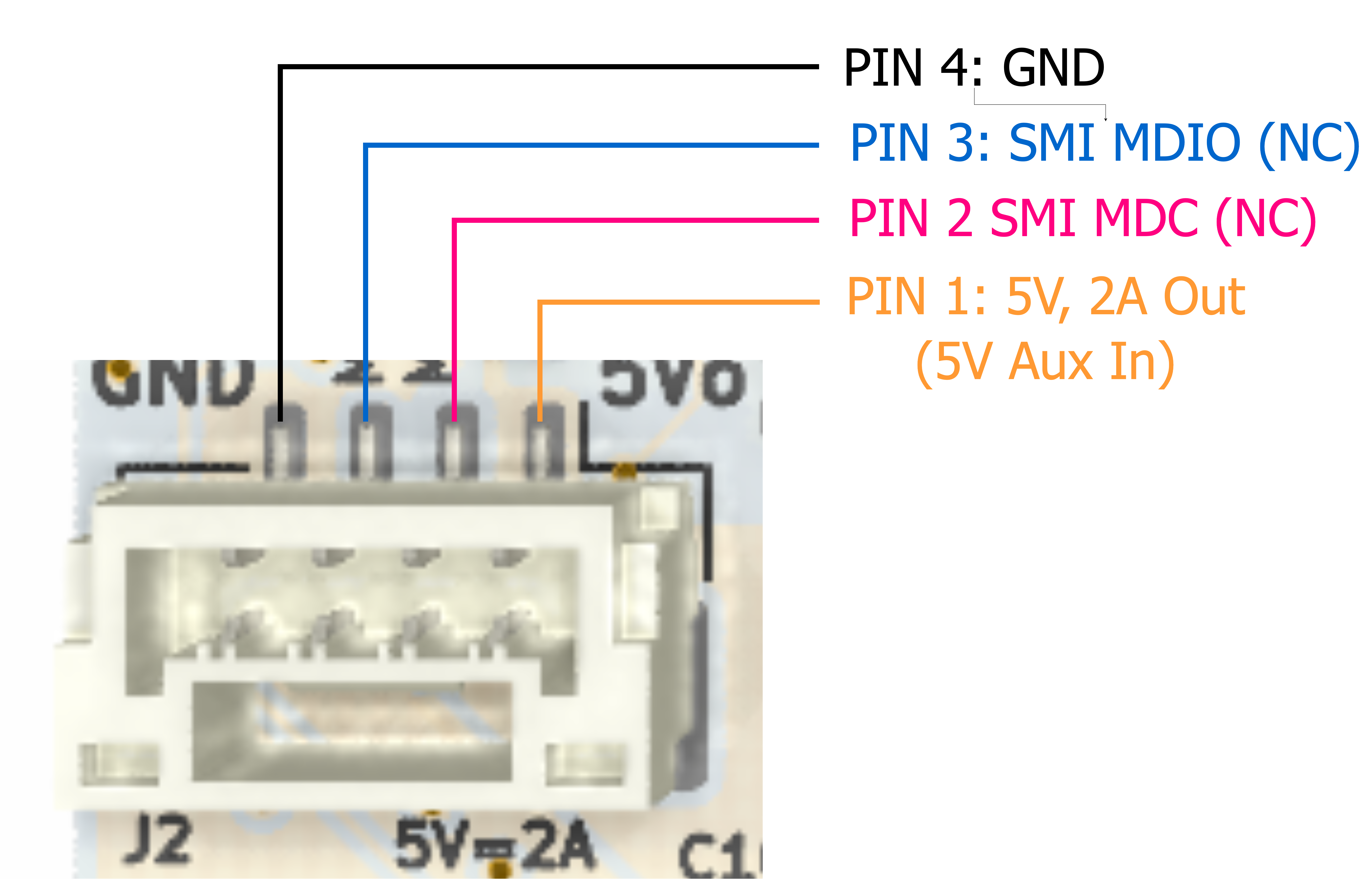
A 5V, 2A supply is available on SwitchBlox Ardupilot when powered from the power input connector. To run SwitchBlox Ardupilot from an external 5V rail, the board's internal DCDC regulator can be bypassed by supply 5V directly into this connector. This can only be done when no voltage is connected to the main power input connector.
Ethernet Switch management control signals are available on pins 2 and 3, which allows direct access to the control registers inside the ethernet switch. These signals are connector to solder jumpers JP1 and JP2 on the board, which are unsoldered by default. To use MDIO and MDC, these two jumpers have to be soldered.
Cables
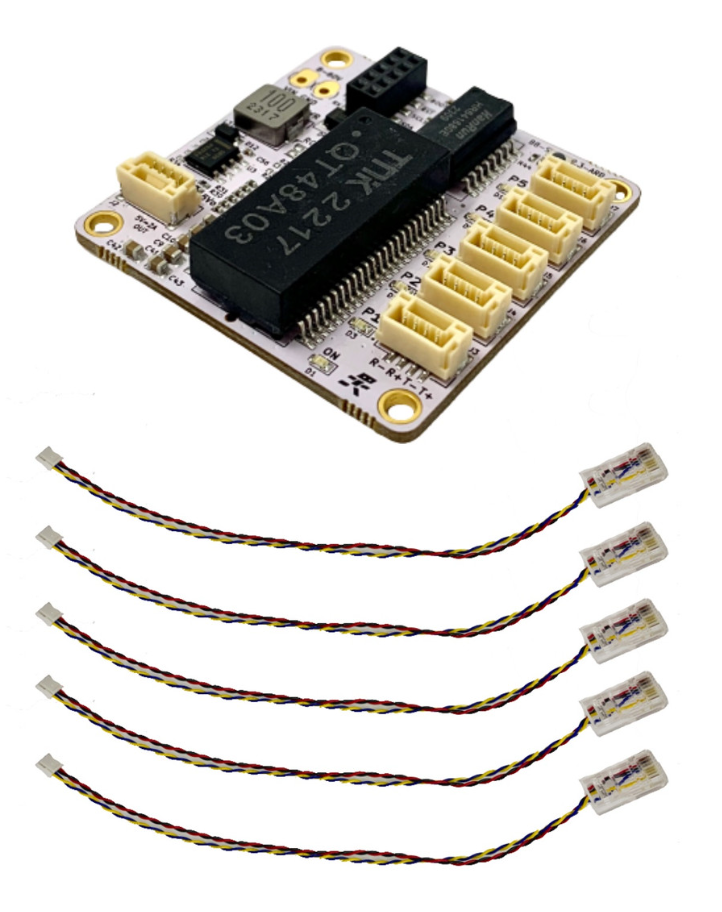
Cable Name: SwitchBlox Ardupilot Data Cable
Number of Cables Included: 5 cables
BotBlox Part Number: BB-RJJST4-1-04-0.2
Function: Converts from SwitchBlox Ardupilot JST connectors to RJ-45 ethernet connectors.
5 data cables are included with SwitchBlox Ardupilot.
Adapter Board
Ethernet's adoption in the Ardupilot ecosystem is not yet standardized, which means different manufacturers use different connectors and pinouts for ethernet. To help solve this problem, we have developed a universal adapter board that is designed to convert between connector and pinout types for the majority of Ardupilot hardware.
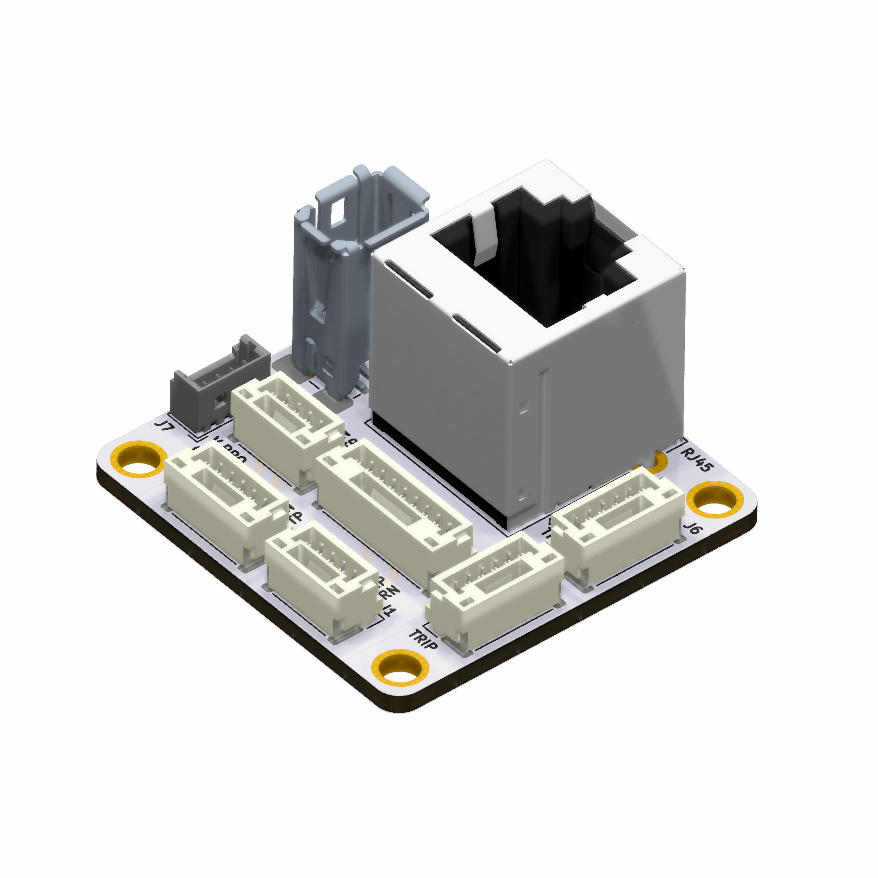
Learn about the adapter board here.
Technical Specifications
| Input Voltage Range | 5-60V (reverse protected) |
| Power Consumption | 300mW (Idle), 700mW (Max) |
| Output Voltage | 5V, 2A |
| Ports | 5 x 10/100Mb ports |
| Operating Temperature |
-10 to 80°C |
| Storage Temperature | -65 to +150°C |
| Dimensions | 38mm x 38mm x 18mm |
| HS Tariff Code | 8517.62.00.20 |
| US ECCN | 5A991 |
- Speed:
- 10/100 Mbps
- Ports:
- 5
| Revision | Subrevision | Part number | Release Date | Notes |
|---|
SwitchBlox, Built for the Ardupilot Ecosystem
Ethernet is quickly becoming the go-to communication bus for drones and robots, and is starting to see more widespread adoption into the Ardupilot ecosystem. To make achieving ethernet communication backbones in Ardupilot systems easier, BotBlox has release SwitchBlox Ardupilot.
SwitchBlox Ardupilot is a modified version of our 5 port 10/100Mbps ethernet switch, SwitchBlox, that uses the 4 pin JST-GH 1.25, for easy connectivity to other Ardupilot compatible hardware.
When used with our Ardupilot Cable Adapter and the included cable set, SwitchBlox Ardupilot can be used with all available Ardupilot hardware that currently uses ethernet.
Ardupilot Compatible Hardware
Newly released Ardupilot devices are starting to see 10/100BASE-TX (10/100Mbps ethernet) incorporated for high speed communications with more advanced sensors. Connecting all these devices together in a drone requires the use of an ethernet switch. SwitchBlox Ardupilot is designed to provide this functionality in an incredibly compact (1.75 inch x 1.75 inch) square, at a low cost and with minimal setup required.
Leveraging our existing SwitchBlox design, which has seen 1000s of flight hours, SwitchBlox Ardupilot provides an easy way to add an ethernet backplane to any Ardupilot powered drone or robot.
Plug and play network switch
As an unmanaged network switch, it works straight out the box, all you need to do is...
- Apply a 8 to 60V DC supply.
- Connect your devices using the included cable set.
- It will automatically begin forwarding packets, no coding or setup needed.
SwitchBlox Ardupilot also has a 5V 2A output for powering small nearby devices. This 5V input can also be used as an auxilliary 5V input to supply the board. Make sure to only use either the 8-60V input OR the 5V Auxilliary input, but not both at the same time.
Board Map
Connector type and pinout
Ethernet Connector
SwitchBlox Ardupilot uses the following connector on board for the five ethernet ports and single power output. This connector system features positive locking and is common in Ardupilot hardware.
Connector On Board: BM04B-GHS-TBT(LF)(SN)
Mating Connector: GHR-04V-S
Mating Connector Crimp: SSHL-002T-P0.2

RX = Receive, input to SwitchBlox Ardupilot
TX = Transmit, output from SwitchBlox Ardupilot
Note, SwitchBlox Ardupilot automatically detects incorrectly connected RX/TX pair and polarity mismatches with a connected device, and will correct its own port connections in this case. This process (part of the ethernet autonegotiation functionality) means you can use a straight or crossover cable, and don't need to worry if you misconnect the polarities of the ethernet signals.
Power Input Connector
Connector On Board: Solder Pads, 2.4mm x 3.5mm with a 1.2mm plated hole
Mating Connector: Bare wires
For power input, SwitchBlox Ardupilot is designed to have power wires soldered directly to the power pads. Alternatively, a 3.5mm pin pitch screw terminal can be soldered to the pads for a more easily removable connection. We recommend the 284391-2 from TE Connectivity for this screw terminal
5V Power Output (5V Aux Input) Connector
Connector On Board: BM04B-GHS-TBT(LF)(SN)
Mating Connector: GHR-04V-S
Mating Connector Crimp: SSHL-002T-P0.2

A 5V, 2A supply is available on SwitchBlox Ardupilot when powered from the power input connector. To run SwitchBlox Ardupilot from an external 5V rail, the board's internal DCDC regulator can be bypassed by supply 5V directly into this connector. This can only be done when no voltage is connected to the main power input connector.
Ethernet Switch management control signals are available on pins 2 and 3, which allows direct access to the control registers inside the ethernet switch. These signals are connector to solder jumpers JP1 and JP2 on the board, which are unsoldered by default. To use MDIO and MDC, these two jumpers have to be soldered.
Cables

Cable Name: SwitchBlox Ardupilot Data Cable
Number of Cables Included: 5 cables
BotBlox Part Number: BB-RJJST4-1-04-0.2
Function: Converts from SwitchBlox Ardupilot JST connectors to RJ-45 ethernet connectors.
5 data cables are included with SwitchBlox Ardupilot.
Adapter Board
Ethernet's adoption in the Ardupilot ecosystem is not yet standardized, which means different manufacturers use different connectors and pinouts for ethernet. To help solve this problem, we have developed a universal adapter board that is designed to convert between connector and pinout types for the majority of Ardupilot hardware.

Learn about the adapter board here.
Technical Specifications
| Input Voltage Range | 5-60V (reverse protected) |
| Power Consumption | 300mW (Idle), 700mW (Max) |
| Output Voltage | 5V, 2A |
| Ports | 5 x 10/100Mb ports |
| Operating Temperature |
-10 to 80°C |
| Storage Temperature | -65 to +150°C |
| Dimensions | 38mm x 38mm x 18mm |
| HS Tariff Code | 8517.62.00.20 |
| US ECCN | 5A991 |
| Revision | Subrevision | Part number | Release Date | Notes |
|---|


