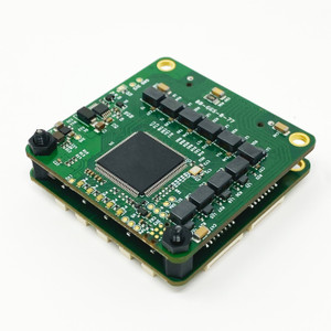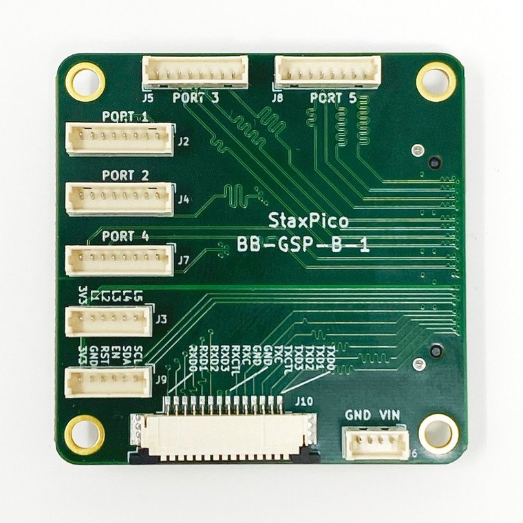
This is the PicoBlade stackable breakout board for GigaStax Rugged.
This board routs all the core signals on GigaStax Rugged onto headers for easy access, this includes:
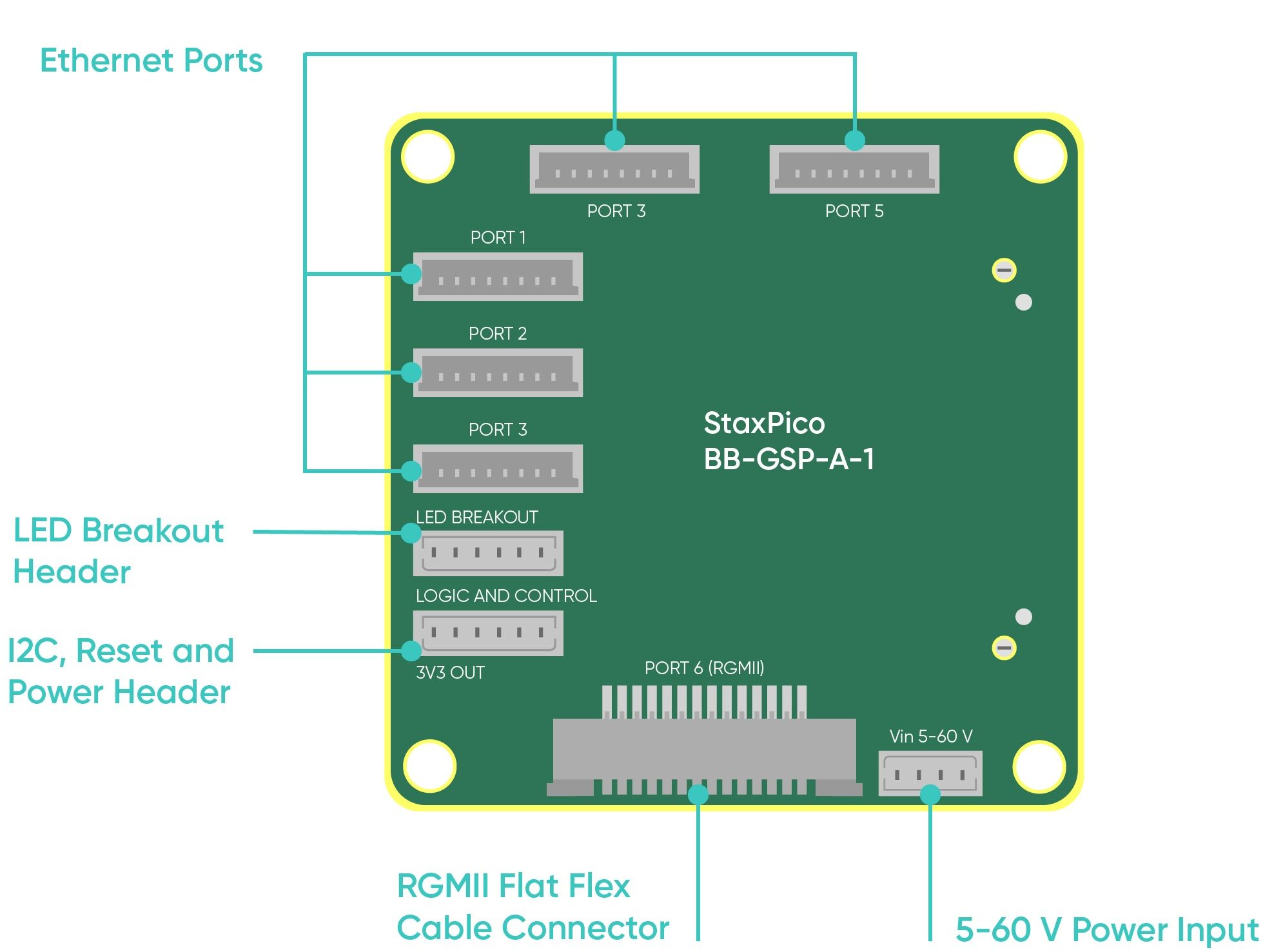
- Five gigabit ethernet ports: Routed onto five PicoBlade headers (using the same mapping as the rest of our boards).
- Power input: Routed onto a PicoBlade header (using the same mapping as the rest of our boards.
- Port Activity LED signals: Common anode port activity LED signals are routed onto a 6 pin PicoBlade header, allowing external port LEDs to be driven to show port activity.
- Ethernet Logic signals: Ethernet logic signals including the I2C management bus, power enable, ethernet reset and 3.3V (Can be used as as power output) are routed onto a 6 pin PicoBlade header. This allows switch management via I2C from an external device.
- RGMII signals: The RGMII signals of the sixth ethernet port are routed onto a FFC connector. This allows two GigaStax assemblies to be connected using an FFC cable to form a 10 port switch.

Design files for this board can be found at the GitHub link below. These are provided to help users developed their own breakout boards.
GigaStax Rugged PicoConn Design Files
Custom Cables
All our boards are shipped with the required 0.3 meter power and data cables included, so you do not need to purchase extra cables. However if you need custom cable lengths for your application, you can order those here.
This is the PicoBlade stackable breakout board for GigaStax Rugged.
This board routs all the core signals on GigaStax Rugged onto headers for easy access, this includes:
- Five gigabit ethernet ports: Routed onto five PicoBlade headers (using the same mapping as the rest of our boards).
- Power input: Routed onto a PicoBlade header (using the same mapping as the rest of our boards.
- Port Activity LED signals: Common anode port activity LED signals are routed onto a 6 pin PicoBlade header, allowing external port LEDs to be driven to show port activity.
- Ethernet Logic signals: Ethernet logic signals including the I2C management bus, power enable, ethernet reset and 3.3V (Can be used as as power output) are routed onto a 6 pin PicoBlade header. This allows switch management via I2C from an external device.
- RGMII signals: The RGMII signals of the sixth ethernet port are routed onto a FFC connector. This allows two GigaStax assemblies to be connected using an FFC cable to form a 10 port switch.

Design files for this board can be found at the GitHub link below. These are provided to help users developed their own breakout boards.
GigaStax Rugged PicoConn Design Files
Custom Cables
All our boards are shipped with the required 0.3 meter power and data cables included, so you do not need to purchase extra cables. However if you need custom cable lengths for your application, you can order those here.


