Posted by Josh Elijah on 16th Jul 2021
SwitchBlox 5V Output Performance
Introduction
SwitchBlox contains a 5V output that can be used for powering downstream devices. This is a really useful feature, so we wanted to provide more quantified data on how this 5V output performs in terms of stability and heat buildup.
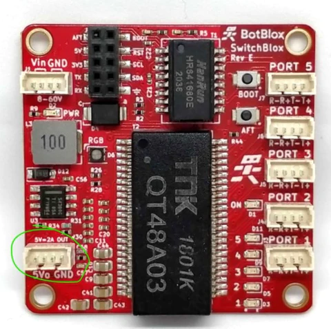
Please note, the results here apply to SwitchBlox Rev E2, however previous versions of SwitchBlox (excluding Rev A) use a similar power output stage.
Test setup
- Ambient temperature = 25°C
- Airflow = 0 LPM
- SwitchBlox operation = 100Mbps networking between two ports
- Input Voltage = 32V
Test Results
0A Output Current
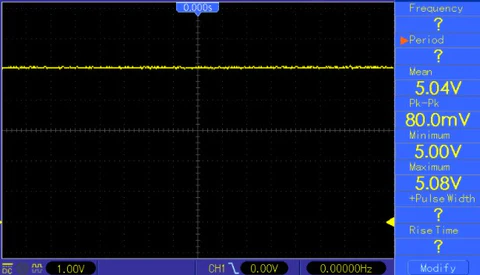
Output Voltage Stability
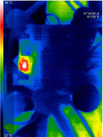
Thermal image of the board at 0A output current
0.5A Output Current
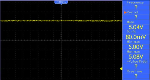
5V Output at 0.5A load current
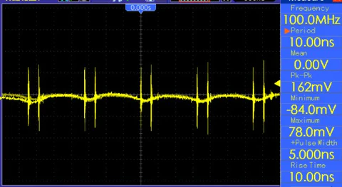
5V Output Ripple (AC Coupled oscilloscope trace) at 0.5A load current
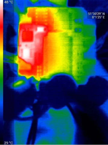
Thermal image of the board at 0.5A output current
1A Output Current
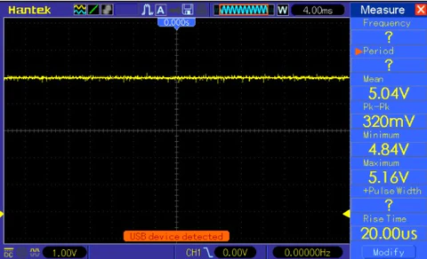
5V Output at 1A load current
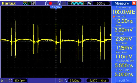
5V Output Ripple (AC Coupled oscilloscope trace) at 1A load current
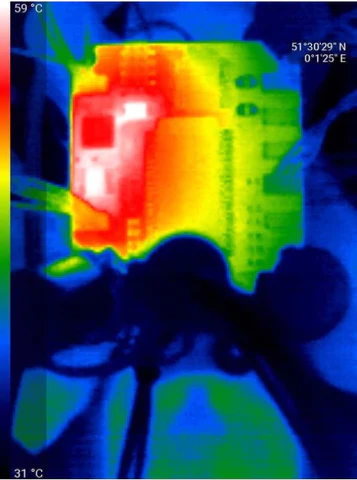
Thermal image of the board at 1A output current
2A Output Current
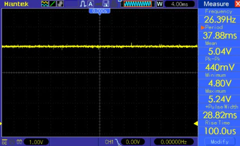
5V Output at 2A load current
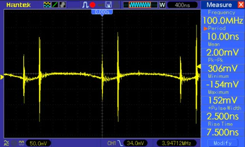
5V Output Ripple (AC Coupled oscilloscope trace) at 2A load current
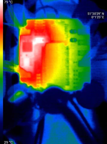
Thermal image of the board at 2A output current
Summary of Results
We can summarise the results above in the table below:
|
Input Voltage |
Airflow |
Output Current (A) |
Voltage Ripple (mV, pk-pk) |
Board temperature rise from 25°C ambient (°C) |
|
30V |
0LPM |
0 |
30 |
11 |
|
30V |
0LPM |
0.5 |
162 |
23 |
|
30V |
0LPM |
1 |
238 |
34 |
|
30V |
0LPM |
2 |
306 |
54 |
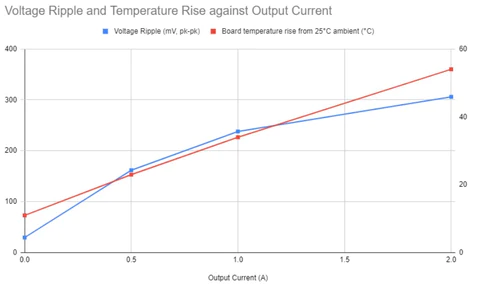
As is clear, both temperature rise and voltage output ripple exhibit a nearly linear relationship with output current. It is also clear that the temperature rise is on two specific parts of the circuitry, shown below.
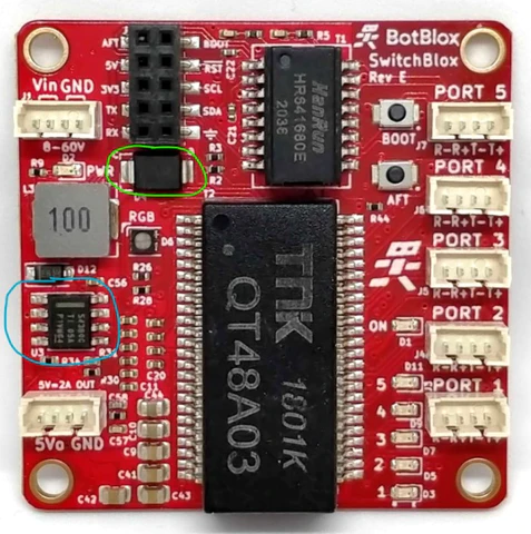
The part circled in blue is the main stepdown regulator, while the part circled in green is the flyback diode on the output of the stepdown regulator. This makes perfect sense as these components are directly on the path of the outgoing current.
Both of these parts have maximum junction temperatures of 125°C, so even at 2A output and a temperature increase of 54°C, this would still allow an ambient operating temperature of around 71°C. However, it would be best practice to facilitate some kind of cooling of these areas to reduce stress on the silicon and give greater headroom on ambient temperature.
In the case of not using the 5V output, no extra cooling is needed on SwitchBlox (in general). For output currents between 0 and 2A, it is best to look at the estimate temperature rise and desired temperature operating range.
