
Posted by Aaron Elijah on 5th Jul 2021
Introduction to SwitchBlox Test Rig
We introduced SwitchBlox, the world’s smallest Ethernet switch in 2017 and it’s been used in a variety of applications from subsea robots, weather balloons and compact industrial infrastructure. To support these applications we’ve developed a test rig to qualify that our products are resilient against electrically harsh environments. In this blog post, we’ll explore what we built, how we built it, and some preliminary results. In particular we are looking at bit rate, packet loss and jitter under ideal conditions (and later when SwitchBlox is subjected to electromagnetic noise).
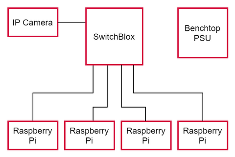
To construct our test rig we mounted SwitchBlox on a platform with five Raspberry Pi 4 Model Bs. These Pis form the network and communicate with each other through the SwitchBlox via Ethernet. We also added a screen to visualise key properties of those Ethernet packets, such as bitrate. The layout we created is shown below. We also added space for the power supply, which provides 20V (range is 5.1 to 60V) to SwitchBlox during runtime.
iPerf3
The actual test we used to quantify the properties of the ethernet connection between the Pis was an iPerf test. iPerf is, according to the iPerf’s Home page, a “tool for active measurements of the maximum achievable bandwidth on IP networks”. What this means in practice is that iPerf runs on a client-server model, whereby we configure one Pi (the client) to send ethernet packets to another Pi on the network (the server) and then repeat those packets back to the client. It’s a simple test to measure the properties of ethernet communication, such as bitrate, etc. One can tune various parameters of the data that the client will send: parameters such as Transport Layer protocol (TCP vs. UDP), the timing between packets being sent and the size of the data.
Actual image of the setup of the test rig with labels
TCP vs. UDP in iPerf
The Transport Layer protocol used to transport the packets in our test is of particular interest; it is either TCP or UDP. TCP is a protocol that sits in the Transport Layer in the OSI model, one above the IP protocol. It facilitates error-checked and reliable communication between two devices (client and server) that are part of an IP network. The simple explanation for the error-checking is that it’s done by the client sending IP packets that form the data as well as data indicating the order in which they’re sent. The server corrects for any packets that are out of order and requests any lost packets from the client. This handshaking between client and server adds latency to the communication but it is vital for communications where lost packets are not acceptable such as file transfer. In contrast, UDP does away with the error checking in favour of less latency. This is frequently used in technologies using Voice-over-IP, where a loss of packets is acceptable as long as the latency is at a minimum.
If we only tested communication using TCP, we would see the bitrate being less than the maximum for SwitchBlox (100Mbps) but we wouldn’t know whether that was down to the board design, external factors or the error-checking. In practice, 100Mbps is never the bitrate of data transported via Ethernet because of the overheads attached to an Ethernet frame. See this link for a table indicating the overheads put on the data at each layer in the TCP/IP protocol suite. The maximum efficiency is 94.93% for TCP/IP and knowing that the UDP header, which replaces the layer 3 TCP header in the Ethernet frame, is 8 bytes instead of 20 gives a maximum efficiency of 95.67% for UDP/IP. This corresponds to a maximum bitrate of 94.93 and 95.67Mbps for TCP and UDP respectively. Therefore, if we achieve a bitrate in our tests close to this maximum, we know SwitchBlox is performing very close to peak efficiency when it comes to speed.
Note that the difference in the speeds between TCP and UDP solely comes down to the error-checking bytes omitted from the TCP header which make up the UDP header. These tests provide a control test, which we will use as a benchmark to measure how EM noise or other external factors affect the bitrate.
SSH logins
Seeing as there is only one screen and a total of five Raspberry Pis forming the network, we need a way for one Pi to control the remaining Pis. This is done by using SSH commands on one client Raspberry Pi, which also acts as the client in the iPerf test, to login to another Pi. Using a single Pi as a local host upon which we can configure server settings on the remaining Pis allows us to continually test a pair of ports one after another and show the results on the same screen with no rewiring and with a very few input commands on the local host Pi. For clarification, when each Raspberry Pi is rebooted, they’re automatically connected to the Wi-Fi, which is the local network which the host Pi will use to control the other Pis through SSH. This is different from the address of the device on the SwitchBlox ethernet network, used for the iPerf tests.
Methodology:
After electing a Pi to be the local host for SSH logins and as the client during the iPerf tests, it is then connected to the 7-inch screen via HDMI. Two command-line terminals are then open on the local host, one controlling the system on the localhost and the other for another Pi controlled by the local host after an SSH login. Finally, we run iPerf tests using TCP and UDP protocol separately. Once that test is finished, we terminate the server session and remotely log out of the external Pi using SSH. Then we configure another iPerf server using another Pi on a different port on the SwitchBlox via SSH login and so forth. Seeing as each Pi is connected to a separate Ethernet port on the SwitchBlox, we can test to see if any of the properties of the ethernet communication vary between ports.
Results:
| SwithBlox (Rev D) Port | TCP/IP average bitrate (Mbit/s) | TCP/IP retransmitted segments | UDP average bitrate (Mbit/s) | UDP average jitter (ms) |
UDP/IP datagrams (%) |
| Port 4->5 | 94.3 | 0 | 95.6 | 0.148 |
0.00% |
| Port 3->5 | 94.3 | 0 | 95.6 | 0.148 |
0.00% |
| Port 2->5 | 94.4 | 0 | 95.7 | 0.195 |
0.00% |
| Port 1->5 | 94.3 | 0 | 95.6 | 0.151 |
0.00% |
One can see that the bitrates achieved at each port pair are remarkably close to the aforementioned maximum rates calculated at 94.93 and 95.67Mbps for TCP and UDP respectively. This verifies our hardware in the ideal case. UDP jitter is also very low, meaning that we have consistent latency across the network . However we recognise that since we are testing a single port pair at a time, jitter was always going to be quite low as the traffic during the test is far smaller than it could be. Nonetheless these initial results are good, especially with perfect packet loss (i.e. none are lost!).
Camera:
SwitchBlox Rev D (and above) is capable of more than just connecting devices to form a network. Each SwitchBlox port is capable of powering devices through Power-over-Ethernet, PoE (compliant with IEEE802.3at for up to 15W of power delivery) technology. This relies on the superposition of a DC voltage on top of the signal voltage used to send Ethernet packets. Lower budget devices, like IP home surveillance cameras, can use a splitter to separate the power and data voltages. This saves cost and minimizes cabling as there is no longer a need for a separate power supply. The flip side is that the SwitchBlox will now need to be powered by at least 44V. In most cases, you’d need this power supply for PoE anyway, so it is trivial to just use it to power SwitchBlox.
Live Stream using PoE:
To test the SwitchBlox’s PoE capability, we form a network consisting of a single Pi and an IP camera. The idea is to stream the data from the camera on the Ethernet network to the Raspberry Pi, which will then display it on the 7-inch screen. The IP camera is connected to a port configured for PoE using the PoE DIP switch on the SwitchBlox, see below. As you can see from the image, Port 1 on the SwitchBlox is PoE -enabled. All but the local host Pis are removed and the IP camera is then connected to the network via this port. After powering SwitchBlox from 48V, the setup is ready for a live stream from the camera. At this point we could then apply electrical noise to SwitchBlox and directly visualise the effect on the camera feed, thereby simulating a realistic situation the SwitchBlox may encounter.
Before data from the camera can be streamed, we need to ensure that we know the host IP address of the camera before we power it up. Usually, IP addresses are set dynamically when devices connect to a network but this would cause a problem as we want to ensure we can always access the camera without constantly having to query it. Therefore, we use the setup guide and software provided by the manufacturer to configure a static IP address and subnet mask on the camera. This means that the network address of the camera is constant. Once we configure the Pi as well, we know both devices will be on the same network.
Camera results:
Now that the Raspberry Pi is configured to be on the same network as the IP camera, we can display the camera’s data using VLC media player. See the video below. There is a delay from my hand moving across the camera and being shown on the screen. This is due to the decoding of the streamed data into something the screen can actually display. It’s unrelated to the Ethernet bitrate not being fast enough as the image data is simply not high resolution enough to create congestion on the network on its own.
Conclusion:
We have successfully constructed a test rig which will allow us to perform stress tests on SwitchBlox and all our future hardware. Our test rig is also scalable to our Gigabit ethernet products (we’re using Pis that have Gigabit ethernet capability). This enables us to quantify exactly what the tolerance of our products are to external factors and how much that deviates from the control test properties we have observed in this experiment. Furthermore, we have demonstrated that PoE works. Given that many of our clients have robot or drone applications, many of which use cameras, knowing how external factors will change the properties of the streamed data is vital.
Next steps:
With our new test setup, we’ve shown our maximum data rates in a low noise, ambient temperature environment. Our next step is to add the ability to apply measurable amounts of electromagnetic noise to SwitchBlox. We’re also running a gamut of tests on PoE including PoE on all ports. Stay tuned for our next post where we publish our results on this!
About the Author:
Aaron Elijah is a software developer with interests in secure networking and cryptography.